Technology
Background | Separation Process| Configuration |
Distillation technology has provided the technology platform for the refinement and recovery of chemicals and solvents for many decades, and has been a key enabler in developing higher levels of quality demanded by high end users such as the Pharma and Microelectronics industries.
This distillation platform engaged in thermal treatment of the solvents combined with catalysis, which produced high end quality products. Over the past 15 years the solvent market has come under increased strain due to ever increasing volume demands combined with fluctuations in combustion fuel prices. Limited capacity, high volumes of hazardous waste and a larger carbon footprint loom large over the industry, and the search for alternative technologies is being backed at the very highest levels in Europe in the form of Framework Programme 7.
The removal of impurities present at ionic level presents a serious challenge to the industry, and GKA Technologies have not only identified processes to address this, but have also generated data to support a new process based on membrane separation science. The process starts with characterisation of the impurities which need to be removed. Typical characterisation methods are completed via GC-MS, GC-FID, ICP-MS and Ion Chromatography as examples. Once the impurities are understood in terms of molecular structure, concentration and the desired level of abundance a separation process will be adapted to suit the purity goals.
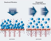
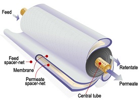
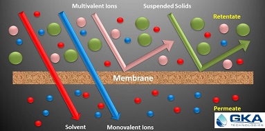
Solvent resistant polymeric and ceramic membranes ensure the separation process takes place in a stable environment, and the process setup can consist of multiples of specially designed membranes in a predefined configuration. A typical membrane cross section below gives a visual representation of the fluid dynamics in the system. Liquids pass over the membrane surface in a cross flow movement under pressurised conditions. A pressure differential (∆P) across the inlet and outlet forces the liquid through the membrane layers and this is collected at the permeate end. Fluid which fails to permeate the membrane is referred to as retentate, and this circulates back into the feed system for reprocessing. The level of permeation (flux rate) is linked directly to variables such as the solvent density, pore size in the membrane wall, resistance created by fractionalization of the membrane surface by the addition of extra layers, pressure and temperature.
The rejection of impurities using membrane technologies is achieved through a number of innovative techniques, such as molecular weight cut off (MWCO) and molecular affinity. If the impurities can be measured by molecular mass, then rejection of the species is possible if it's molecular mass exceeds the molecular weight cut off of the membrane pores. A basic illustration of this principle is set out below;
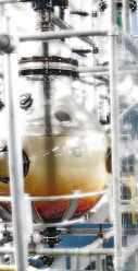
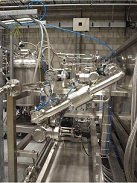
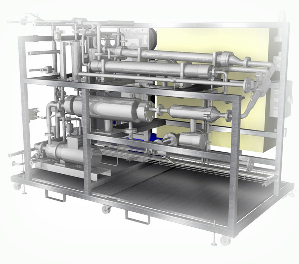
The configuration of the separation process is extremely important, especially when dealing with multiple levels of separation in series. This type of configuration is set out in the example below, which is a schematic of a type 'A' membrane in parallel followed in series by Type 'B' membrane which is also running in a parallel setup. The parallel configuration offers greater capacity, while the in series configuration offers greater degrees of separation, depending on the target species. The process technology can be designed and built as a fresh installation, as observed in Figure 1 below, but due to the process flexibility, the option of a 'retrofit design is also possible. Figure 2 is a 3D image of the pilot plant used for validation of the technology.
Aside from the separation science, there are also engineering issues which must be addressed within the configuration. Pressure, temperature and flow regulation is paramount to a steady flux and separation ratio, but also to a safe and controlled process. GKAT is working with its partners to deliver comprehensive separation/process solutions based on this new technology.
Figure 1. Sample Separation Plant in both parallel and series arrangement
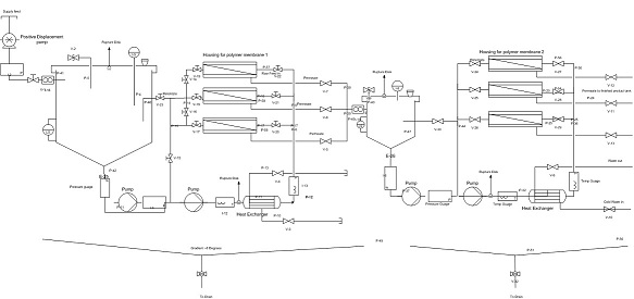
Figure 2. Pilot Plant used for Demonstration of new Technology.
|